Remtech © 2025

10,000 Environmental Remediations Since 1975
24 Hr Emergency Response
800-377-3648
| Careers |
| Contact Us


SPILL RESPONSE, EMERGENCY RESPONSE
▶︎ Disaster Response and Disaster Restoration
ENVIRONMENTAL REMEDIATION, ENVIRONMENTAL CLEANUPS
▶ Groundwater Vacuum Extraction and Multiphase Extraction
▶ Bioremediation Accelerator and Cleaner - HC-2000
▶ Mold Remediation, Mold Removal
▶ Mercury Cleanup at Manufacturing Plant
▶ Homeless Encampment Cleanups
INDUSTRIAL TANK CLEANING AND MAINTENANCE
▶ Industrial Cleaning, Industrial Maintenance, Tank Cleaning
▶︎ Sewer Cleaning, Pipeline Inspection and Cleaning
▶︎ Confined Space Entry and Cleaning
▶ Confined Space Rescue Services
▶︎ Combustible Dust Cleaning and Dust Hazard Analysis
▶ Combustible Metal Dust Cleaning and Hazard Analysis
▶︎ Hi Rail Vacuum Truck Services
▶ Robotic Vacuum ROV Cleaning and Dredging
▶ Fall Protection, Loading Racks, Access Grating and Steps
▶ Landfill Maintenance and Operation
ENVIRONMENTAL DESIGN BUILD
▶︎ Environmental Remedial Design and Construction
▶ Biogas and Landfill Gas to Energy Systems
▶ Pollution Prevention, Spill Prevention Facilities
WASTE MANAGEMENT & MOBILE WASTE TREATMENT
▶︎ Waste Pickup, Transport and Disposal
▶ PFAS Treatment and PFAS Rapid Testing
Our multi-disciplinary team of environmental professionals provide proven environmental remediation and cleanup services, resources, and mobile treatment solutions that will withstand the test of time and changing regulations. Remtech reduces the layering of firms, liabilities, completion times, and project costs by providing single source turnkey solutions. Our extensive experience allows us to select “smart” cost-effective and sustainable solutions that work.
Remtech Engineer's principals have completed over 10,000 environmental remediation and cleanup projects since 1975. Remtech’s principals have over six (6) decades of multi-disciplinary experience in spill response, environmental remediation, mobile wastewater treatment, renewable energy, PFAS mobile treatment, hazardous waste management, industrial cleaning and maintenance, stormwater management, tank cleaning, confined space cleaning, disaster response and recovery, vacuum truck services, ROV robotic vacuum cleaning and dredging, environmental engineering consulting, and environmental OSHA, DOT, and EPA training. Remtech's principal service area includes Georgia, Tennessee, Alabama, North Carolina, South Carolina, and Florida. Remtech's Corporate Headquarters is located in Atlanta, Georgia.
Remtech's project management is conducted by professionals that are board certified by the American Academy of Environmental Engineers and Scientists, Institute of Hazardous Materials Management, and Certified Safety Professionals in Hazardous Materials, Environmental Remediation, Waste Management, Water, and Wastewater Engineering. This ensures that reliable, and cost-effective solutions are implemented on your projects. Remtech also conducts forensic investigations that documents root cause(s) that provides evidence to recover damages from responsible parties. In addition, Remtech crisis management approach "returns out of control" events to manageable projects that minimizes operational down time and costs.
Remtech's tenured success record in the environmental services industry has allowed Remtech to become a preferred environmental services company to a variety of clients including; railroad, military, aerospace, energy, power, transportation, chemical, petrochemical, refinery, manufacturing, pipeline, agricultural, food, healthcare, pharmaceutical, hospitals, waste management, and institutions.
REMTECH BROCHURE
4-Day Bench-Scale Soil Slurry Diesel (TPH) Degradation Product Comparisons (Fuel Buster - 7 Days) Out Performs Competition
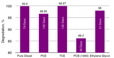
HC-2000 Bench-Scale Soil Slurry for Diesel, PCE, TCE, PCBs and Ethylene Glycol Degradation Times

Freshwater 96-Hr, LC50 Aquatic Toxicities(Silverside, Mendia Beryllina) Less Toxic than Competition


Remtech Engineers Environmental Services Video


HC-2000 Removes Mineral Oil Stains from Substation Gravel
HC-2000 Cleans Transformer Shell After Power Plant Fire
HC-2000 Purchase through Remtech Store
Remtech has developed a proprietary slow-release bioremediation and biosurfactant that accelerates native heterothropic bateria degraders, HC-2000 (HC2), that cleans, disinfects, desorbs, reduces odors and degrades fuels and sheens, oils, transformer oils, lubricants, chlorinated and non-chlorinated solvents. HC-2000 biostimulation agent works on soil, ballast, gravel, groundwater, surface water, wastewater, sludges, septic tanks, power substations, cleaning surfaces (clothing, concrete, asphalt, metal), and other surfaces. Biosurfactants increase mass transfer of biochemical reaction accelerators to rapidly degrade and clean petroleum based contaminates. Slow release ingredients continue to deliver active ingredients over periods exceeding 1 year.
HC-2000 has been used successfully on over 400 site remediations during the past 20 years. HC-2000 is a Green Sustainable Technology that enhances the natural degradation process and accelerates the degradation of refined solvents and petroleum based compounds in soil, groundwater, surface water, railroad ballast, power plants and substation gravel, ASTs with grounding systems and other media. HC-2000 is a more efficient and cost-effective degrader and less toxic than many competing products. Remtech's Bioremediation Design Optimization Primer with HC-2000 is presented here. HC-2000 is approved by Florida, Georgia, and by other states on a case-by-case bases. Georgia Approval Letter, Florida Approval Letter, HC-2000 SDS. Remtech's BioPile Bioremediation Design Optimization Primer with HC-2000 is presented here.


STORMWATER FACILITY, POND & BASIN SERVICES
▶︎ Stormwater Facility, Pond and Basin Due Diligence
▶ Stormwater Facility, Pond and Basin Inspections
▶ Stormwater Facility, Pond and Basin Maintenance
▶ Stormwater Facility, Pond and Basin Design Build
▶ Stormwater and Pollution Control Facilities
ENVIRONMENTAL CONSULTING
▶︎ OSHA, EPA, DOT Hazmat Training
▶︎ Spill Prevention and Facility Response Plans
Bioremediation Accelerator Video HC-2000

BIOREMDIATION ACCELERATOR HC-2000 OUTPERFORMS COMPETITION
ENVIRONMENTAL REMEDIATION AND SPILL RESPONSE CONTRACTOR

FRACAIR DOWNLOAD